Getting started with the ESP8266

The ESP8266 is a popular and low-cost WiFi-enabled microcontroller that has gained a lot of attention from makers and developers in recent years. It’s a powerful and versatile device that can be used in a wide variety of projects, from home automation and IoT devices to robotics and wearable tech. If you’re just getting started with the ESP8266, this post is the perfect place to start.
In this post, we’ll cover the basics of what the ESP8266 is, what it can do, and how to get started using it. We’ll also look at some popular development boards and programming environments, as well as some useful resources for learning more about the ESP8266.
Whether you’re an experienced maker or a beginner, the ESP8266 is a great device to have in your toolkit. So let’s dive in and learn more about this powerful microcontroller!
Which ESP8266?
If you had a chance to visit some online shop, odds are that you got confused to the amount of different ESP8266 boards there are on the market. First and foremost, let’s have a quick breakdown of this board madness:
- ESP-01: the smallest and the cheapest of all the ESP8266 modules available. It has a small form factor and has only eight pins, making it perfect for small IoT projects with limited input/output requirements. It comes with a built-in antenna and has a 1MB flash memory.
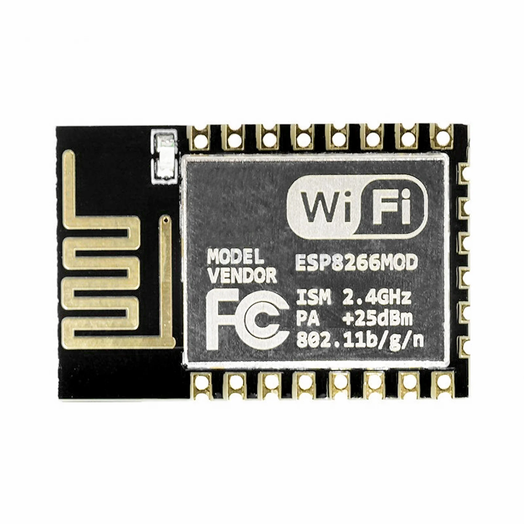
- ESP-12E/F: one of the most commonly used ESP8266 modules. It has a larger form factor than ESP-01 and comes with 22 pins, including GPIO, I2C, SPI, and UART interfaces. It has a built-in antenna and has 4MB of flash memory.
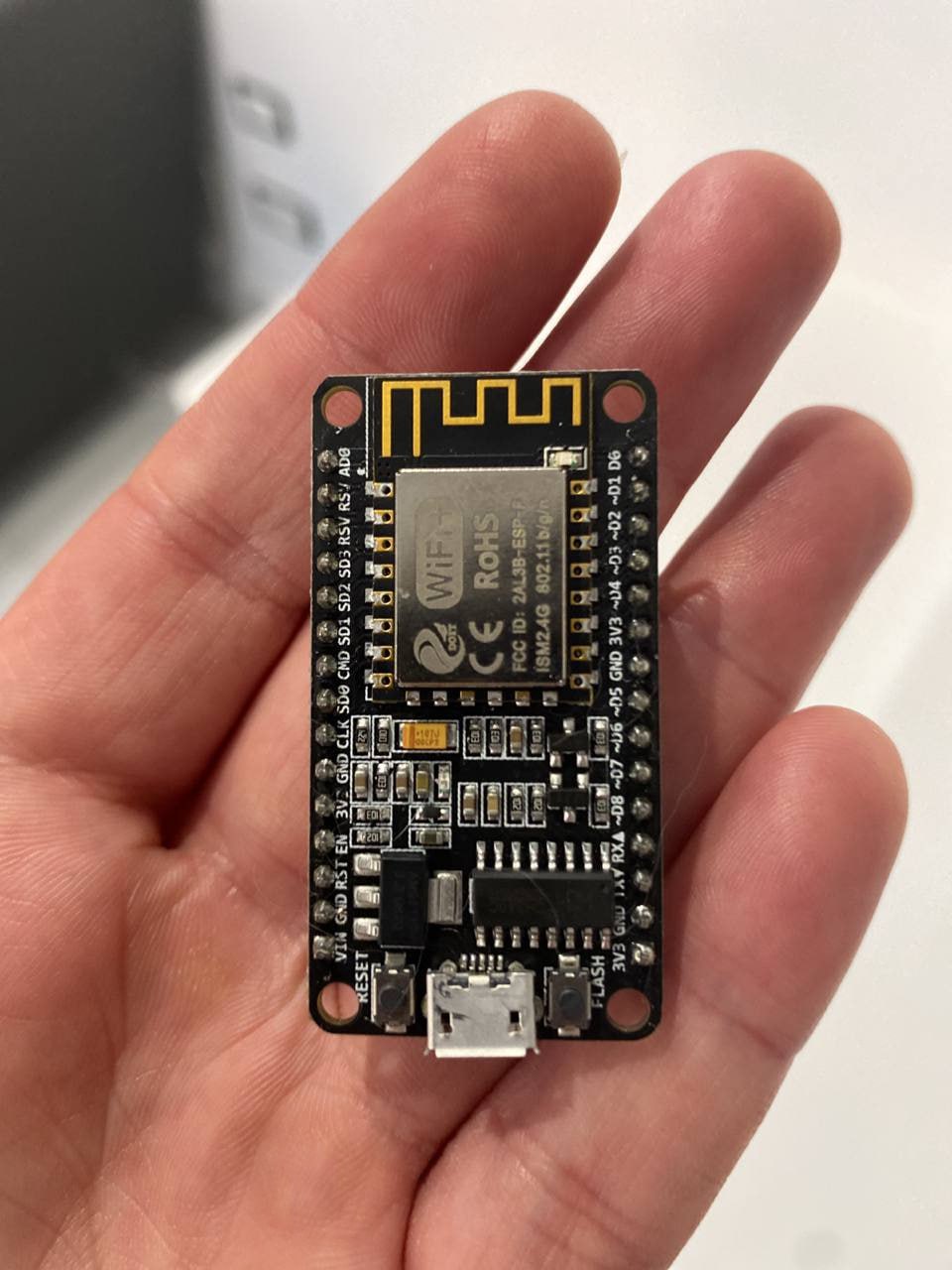
- NodeMCU: development board based on the ESP8266 module. It has a USB-to-serial converter, voltage regulator, and an ESP-12E module on board. It comes with a built-in Wi-Fi antenna, and the pins are conveniently placed, making it easy to use for prototyping. It has 4MB of flash memory and is compatible with the Arduino IDE.
- Wemos D1 Mini: small-sized development board based on the ESP8266 module. It has 11 digital input/output pins, one analog input pin, and is compatible with the Arduino IDE. It also comes with a built-in USB-to-serial converter and a micro-USB port for power supply. It has 4MB of flash memory.
- ESP32: is an advanced version of the ESP8266 module. It has dual-core processors, Bluetooth, and Wi-Fi connectivity. It has 520KB of SRAM and 4MB of flash memory. It also comes with more GPIO pins, I2C, SPI, UART, and other interfaces. ESP32 is a more powerful module and is suitable for more complex IoT projects.
I personally work with the NodeMCU for developing stuff, while I normally use ESP-12E/F for prototypes / production projects. Indeed, the NodeMCU comes with a handy 5V-powered USB port, which is used to both upload code on your board and to power it on. The ESP-12E/F do not have a USB port, as they are typically soldered on actual circuit boards (we’ll have a separate post about them).
It helps to think about the NodeMCU as a ESP-12E/F + additional stuff useful for development / prototyping.
What an ESP8266 can do for you?
It’s amazing the number of things this tiny box allow you to do. A few examples:
- Monitoring: you can connect it to an incredible number of sensors. Thanks to the built-in wifi antenna, you can store / process sensor data in-cloud.
- Home automation: there are plenty of libraries supporting standard protocols (Zigbee, Knx, Modbus just to name a few) for any kind of home-automation related projects.
- Robotics: plug your sensors, actuators, wheels, lasers.. write your custom logic, and build the next Godzilla!
- Wearables: yes, you can even build your custom-made smart watch with an ESP8266.
- Education, WebServers, Alarms and so on!

The NodeMCU has plenty of useful pins:
- VIN: The input voltage pin, which can accept a range of voltages from 4.5V to 9V DC.
- GND: The ground pin.
- 3V3: The output voltage pin that provides a regulated 3.3V DC supply.
- EN: The enable pin. This pin is used to enable or disable the NodeMCU.
- RST: The reset pin. This pin is used to reset the NodeMCU.
- D0-D8: General-purpose digital I/O pins that can be used for input or output. Note that D3 and D4 are used for I2C communication and D1 and D2 are used for UART communication.
- A0: Analog input pin.
- SDA: I2C data pin.
- SCL: I2C clock pin.
- TX: UART transmit pin.
- RX: UART receive pin.
- GPIO16: A special-purpose pin that can be used for wake-up from deep sleep.

The ESP-12E/F, though, exposes different pins:
- VCC: The input voltage pin, which can accept a range of voltages from 3.0V to 3.6V DC.
- GND: The ground pin.
- TXD: UART transmit pin.
- RXD: UART receive pin.
- CH_PD: The chip enable pin, which is used to enable or disable the ESP8266.
- RST: The reset pin. This pin is used to reset the ESP8266.
- GPIO0: General-purpose digital I/O pin that can be used for input or output. This pin is also used to determine the boot mode of the ESP8266.
- GPIO2: General-purpose digital I/O pin that can be used for input or output. This pin is also used for the built-in blue LED on the NodeMCU.
- GPIO4-GPIO5 / GPIO12-GPIO15: General-purpose digital I/O pins that can be used for input or output.
So, get yourself a NodeMCU on AliExpress for a few bucks, then jump in the next post where we’ll kickstart our very first project!
Made with ❤️ by Mikepicker